
© 1998-2005
Raztek Corp.
top of page
top of page
top of page
top of page
top of page
top of page
top of page
top of page
top of page
top of page
top of page
top of page
top of page
top of page
top of page
top of page
top of page
top of page
top of page
top of page
top of page
top of page
top of page
top of page
top of page

Articles:
Electroheating™
Ohmic Heating
Rapid Vacuum Cooler (CIP)
![]()
-
Electroheating™
David Reznik
 Electroheating™ is today’s modern technology for heating fluids in the
food and drug industries for the purposes of sterilization and pasteurization.
Electroheating™ is the product of more than ten years of engineering and food processing
research and development by Raztek Corporation. It is a proven technology, now in its
third generation, with industrial applications up and running. Raztek’s
Electroheating™ customers are enjoying extensive benefits of the technology over
conventional heat exchanger methods including fast heating rates, more uniform heating and
improved product safety and quality.
Electroheating™ is today’s modern technology for heating fluids in the
food and drug industries for the purposes of sterilization and pasteurization.
Electroheating™ is the product of more than ten years of engineering and food processing
research and development by Raztek Corporation. It is a proven technology, now in its
third generation, with industrial applications up and running. Raztek’s
Electroheating™ customers are enjoying extensive benefits of the technology over
conventional heat exchanger methods including fast heating rates, more uniform heating and
improved product safety and quality.
Principles of Electroheating™
Electroheating™ is based on passing electrical current through a food or biotech fluid by application of a voltage source across electrodes, which are placed in contact with the product. Since a fluid will present an electrical resistance to the current, it will be rapidly heated in proportion to the square of the magnitude of the current. This well-known law of electrical engineering is depicted below in Figure 1.
Figure 1. Scientific Basis of Electroheating™
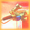
The challenge, of course, is implementing this principle at industrial scale as a practical alternative to conventional heat exchanger based approaches for food processing. Raztek’s multidisciplinary experts, with backgrounds and experience in engineering and food science, have developed the equipment and methods to accomplish this industrialization. The patented Raztek Electroheater, depicted in its Pilot plant configuration in Figure 2, is the fundamental building block for Electroheating™.
The Electroheater enables a fluid in a continuous flow system to be rapidly and accurately heated. Originally powered by RF voltage, Raztek’s current third-generation Electroheating™ systems feature use of common high voltage AC power available worldwide at 50 or 60 Hz. The Raztek Electroheater is constructed of non-conductive FDA-approved materials such as GE Ultemä . Specially treated, pure-carbon electrodes are employed to avoid metal dissolution by electrolysis. Raztek’s full-scale industrial Electroheating™ systems are multistage units as depicted in Figure 3, configured to take advantage of cost effective three-phase AC power delivery systems.
Figure 2. Pilot Scale – Single Phase Unit
Figure 3. Full Scale Industrial System Block Diagram
Advantages of Electroheating™Electroheating™ provides several unprecedented advantages over conventional heat exchangers that inherently develop temperature gradients between a heated surface and a product.
- Very Rapid Heating. In the Electroheating™ system, electrical current flow through the product generates heat instantaneously. Consequently, the food or biotech product experience very rapid heating – typically a rise of 100°F / 55°C can be achieved in less than 0.1 second. In addition, the pure carbon electrodes employed have some reducing effect.
- Uniform Heating of the Product. Current flow is uniform through the bulk of the homogeneous product and heating is likewise uniform, with no temperature gradient perpendicular to the fluid flow. Thus, the hot surface effects of heat exchangers such as scorching and fouling may be avoided. This not only favorably impacts product quality, but can also reduce the costs of maintenance and system downtime.
- Temperature Accuracy. The Electroheating™ system is configured with a thermocouple- based feedback mechanism that is interfaced to an SCR controller to regulate the applied voltage. This allows setting temperatures to high accuracy and resolution.
- Instant On-off. There is no residual heat in the system when the current is shut off. This is not the case in a conventional heat exchanger, which has relatively large thermal mass and, thus, retains heat even when the operation has stopped.
- Small Equipment Footprint. Practical Electroheating™ installations can be installed within less than a square foot of floor space. Industrial scale installations are usually configured as six Electroheater sections (see Figure 3 on the previous page), each approximately a foot in length. In all cases, the heating device becomes part of the tubing and consumes considerably less plant space than an alternative heat exchanger.
- Process Improvement. Electroheating™ offers opportunities to raise food temperatures to higher levels than conventional heat exchangers. Pasteurization and sterilization are a function of temperature and time; the higher the temperature, the shorter the required holding time. In addition, electrical current can damage the reproductive system of some microorganisms. This offers the possibility to reduce the temperature and/or holding time, which may favorably impact the quality of some foods. In one case, the ability to increase the process temperature for liquid eggs resulted in longer shelf life, virtually eliminating return costs for our customer while providing added safety for the consumer.
Whether your business is food or biotech products, you can improve your operating profits and product quality through Raztek’s Electroheating™ technology. Raztek has demonstrated the effectiveness of Electroheating™ in a wide variety of food products. Fruit juices and concentrates, shelf-stable milk, puddings, soups and liquid egg products can be heated rapidly, uniformly, and effectively without risking the organoleptic properties of the product. In addition animal blood and other heat sensitive proteinaceous fluids in the biotechnology industry have been successfully processed using the Electroheating™ system.
Testing Electroheating™ for Your Products
Raztek offers experimental runs on the Electroheating™ system at its facilities in Sunnyvale, California, in order to produce samples and establish the feasibility of implementing the technology. Manufacturers who feel the system may have benefit within their market are encouraged to contact Raztek Corporation for a demonstration.
Upon successful completion of the experimental tests, Raztek can install a low-invasive pilot scale Electroheater in your plant, staffed by highly experienced Raztek experts working closely with your own team. This installation will enable testing of Electroheating™ as applied directly to your products under volume production conditions, prior to the industrial scale installation.
Ohmic Heating of Fluid Foods
Food technology May 1996
Various parameters affect the performance of ohmic heating devices used to heat fluid food products.
David Reznik
OHMIC HEATING, ALSO CALLED RESISTANCE heating, Joule heating, or Electroheating™ (Raztek Corp., Sunnyvale, Calif.), is based on the passage of alternating electrical current through a food product that serves as an electrical resistance. The electrical power introduced into the product is translated into heat. The electrical currents passed along or across the flowing fluid.
The obvious advantage of ohmic heating over conventional heating is the departure from the limiting heat transfer coefficient and the need for high wall temperatures. Such limitations of conventional heating of viscous proteinaceous products, such as cheese, may be expressed in reduced heating rates, the need for large heating surfaces, and the risk of fouling and burning of the product. At first glance, ohmic heating seems straight forward, but for efficient implementation in the food industry, many factors have to be carefully considered and accurately quantified.
Factors to Be Considered
Since there is very limited experience in ohmic heating on industrial scale, all the parameters that could be involved must be considered in the process design. Many of these parameters have parallels in conventional heating, but their magnitudes and the specific effects may be very different.
Electrolysis. Alternating current at low frequency such as 50 and 60 cycles has an electrolytic effect similar to that of direct current, though to a lesser extent. The major electrolytic effect is the dissolution of the metallic electrodes, which may contaminate the product. One way to overcome this problem is to utilize high frequency. At alternating frequencies above 100 kHz, there is no apparent metal dissolution. Stainless steel electrodes operating for more than three years in the industry show no marks of any metal dissolution and no need for replacement. Also, insoluble, specially treated, pure carbon electrodes enable use of more readily available electrical power at a frequency of 50 or 60 cycles.
Electrical Resistance. Perhaps the most important factor is the specific electrical resistance of the product and its change with temperature. The specific resistance is the electrical resistance of the product between two 1 cm2 electrodes located 1 cm apart. In other words, it is the electrical resistance of 1 cm3 of the product, and it has the units of ohms/cm2/cm. Unlike metals, where the resistance increases with temperature, this specific resistance decreases with temperature by a factor of 2-3 over a 120° C temperature rise.
The actual resistance of the ohmic heating device is a function of the specific resistance of the product and the geometry of the device:
R = (Rs)(d)/(A) (1)
where R is the total resistance of the device or a selected section of it in ohms, Rs is the specific resistance in ohm cm, d is the distance between the electrodes in cm, and A is the area of the electrodes in cm2.
The resistance will determine the current:
R = V/I (2)
Where V is the voltage in volts and I is the current in amperes. Transformers and other electrical equipment have limitations on current, and these dictate the choice of the optimal resistance, which in turn dictates the geometry of the ohmic heater. If the resistance is too high, the current at the maximum voltage will be too low and therefore the power will be too low. If the resistance is too low, the maximum limiting current will be reached at low voltage, and the power will be low. To make the best use of the available power, the resistivity of the product has to be studied and carefully considered in the design.
Power Consideration. The heating requirement per hour is calculated by multiplying the mass flow rate M in kg/hr by the specific heat Cp in kcal/kg/°C and the temperature rise in °C:
Q = MCp delta T (3)
Since 1kW-hr = 860 kcal, power P in kW is Q/860. But also P=VI and P= RI2. Once the power is known, the next factor to be considered is the current density, which also depends on the available voltage. Since P/ V = I, the total current is known. This value of total current divided by the critical current density will dictate the area of the electrodes.
Voltage. The maximum standard power line is 460 ± 20 V in the United States. Using this relatively low voltage will require high currents to achieve the required power.
As mentioned, there are maximum current limitations to be considered. It is therefore prudent to raise the voltage, using transformers, to enable the use of low currents. Transformers that can provide 12,000 V at various power levels, for example, are readily available. The power specification of the transformers should be about 30% higher than the power requirement. This will compensate for minor changes in power demand, eliminate the need to use the maximum voltage and current, and allow some flexibility in the design of the ohmic heater.
Current Density. This is one of the most critical parameters. It is the current divided by the area of the electrode. Every product has a specific critical current density above which arcing is likely to occur. So once the limiting current density is known and the total current has been derived from the already known power and voltage, the minimum area of the electrode is dictated. Since the resistance is a function of the area, the distance between the electrodes is already dictated.
As a matter of fact, since all of the above parameters are interrelated, there are no degrees of freedom left, and the geometry of the device for the specific utilization is dictated. Forcing geometrical dimension will require a change in one or more of the other parameters. The geometry determines the resistance, which determines the current.
Decreasing the distance between the electrodes, for example, will decrease the resistance, which will increase the current to perhaps beyond the maximum critical value, which in turn may lead to arcing.
Ideally, a low total current should be utilized. This requires a high resistance, which dictates a small crosssectional area and/or a long distance between the electrodes.
Changing the distance without changing the area will increase the resistance and volume between the electrodes, but also will decrease the power, which means that the temperature will not rise to the desired level.
The solution is to use sufficiently large electrodes connected by a narrow tub, since the current density is critical only near the electrode. Practically, the heating takes place in the narrow tube only, where the area A in Eq. 1 is not that of the electrode and therefore does not affect the critical current density.
The burden is put now on the pumps, since the narrow tubes create a highpressure drop. This shifting of the burden is similar to shifting the burden from the current to the voltage to reach the required power.
Such considerations have led to the development of ohmic heating devices that can raise the temperature of large volumes of fluid by about 9000° F/sec. A temperature rise of 160° F in 0.02 sec, for example, has been achieved in a commercial implementation.
The actual dimensions of the ohmic heater range from a 6ft long tube with an external diameter of 3 in. for heating thousands of gallons/hr to a <1ft long tube with an external diameter of 2 in. for heating hundreds of liters/hr. Typical internal diameters of the tubes are 1 in. for the large unit and 1/8 in. for the small one. In all cases, the ohmic heating device becomes a part of the tubing.
Velocity and Heating Rate. The velocity of the product in the ohmic heater is critical for applications with high temperature rise, especially for proteinaceous products where some coagulation of proteins may occur.
Arcing may occur when the material or part of it changes phase to a solid or gas. When material solidifies and remains in the ohmic heater, it becomes overheated, which may reduce the flow rate and increase the resistance. This in turn may lead to boiling of the liquid at the electrode, which leads to arcing. It is therefore important in some applications to induce a turbulent flow and keep the pressure well above that of the boiling point.
In ohmic heating, the energy is introduced by the electrical current, which flows at the speed of light. The velocity and the resulting turbulence in conventional systems facilitate rapid mixing and therefore enhance heat transfer by maintaining a maximal temperature gradient. In ohmic heating of homogeneous fluids, there is no temperature gradient, since the temperature is uniform across the crosssection of flow.
Compared to the velocity of the electrical current, the velocity of the product is negligible, and the current flows as if the product is still. However, when the velocity of the product is not uniform in the crosssection, the dwelling time of the slower moving fluid in the ohmic heater is longer. With ohmic heating systems that heat at a rate of 5,000° C/sec, a very small delay will lead to a very high difference in temperature. It is therefore important to avoid even small differences in velocity in the cross section.
With extremely high heating rates, and when proteinaceous products such as liquid egg are ohmically heated, it is important that the velocity of the fluid be maintained uniform along the tube and the current line.
Use of a constant average flow rate per minute or even per second may not be good enough, since low frequency pulses may lead to an increased holding time.
It is very important, therefore, to avoid pulses that are longer than about 1% of the dwelling time of the product in the ohmic heating zone. If the total dwelling time is 0.02 sec and the ohmic heater raises the temperature in this short time by 100° F, then a 0.002sec pulse, in which the fluid actually stops, will cause an extra 10° F temperature rise. This may lead to undesirable results, which should be avoided by choosing suitable pumps.
Holding Time. Ohmic heating is usually used for pasteurization and sterilization of food and other biological products. The product has to be held at the peak temperature for a certain period of time to ensure that desired level of bacterial kill.
Ohmic heating the product to the same temperature as in conventional heat transfer technology will demand the same or shorter holding time. Elevating the temperature to unprecedented peak temperatures will enable shorter, also unprecedented, holding times.
The holding time of ohmically heated material may be shorter than for conventionally heated products heated to the same peak temperature, since the electrical current can damage the reproductive system of some microorganisms. This offers a possibility to reduce holding time or even reduce the heat-treatment temperature.
Design Considerations.
Designing an ohmic heater for a particular application is somewhat more specific than designing or choosing a heat exchanger. To optimize the ohmic heating process and benefit from its potential advantages over conventional heating, the ohmic heater should be tailored to the specifications of the application. These include the following:
Type of Product. The electrical conductivity of the specific product and its change over the range of the temperature rise are the major parameters for the design.
We usually ask for a sample of the product and measure its resistivity in the relevant range of temperatures. In some cases, different formulations of the same product may differ significantly in resistivity. Salt-added formulations may have half the resistivity of a non salted product.
Flow Rate. The maximum flow rate will determine the power requirement.
Temperature Rise. The temperature of the product at the heater entrance and exit determines the power requirement and the resistivity.
Holding Time. Using ohmic heating may offer an opportunity to raise the temperature to much higher levels than used in conventional heat exchangers. Pasteurization and sterilization are a function of temperature and time; the higher the temperature, the shorter the holding time.
When applying unprecedented high temperatures in ohmic heating, the corresponding adequate holding times have to be reestablished. To take into account the effect of the temperature and the electrical current on bacterial kill, an ohmic heater can be used on a pilot line or preferably a production line.
Based on a paper presented during the IFT Food Engineering Division symposium, "Ohmic Heating for Thermal Processing of Foods: Government, Industry, and Academic Perspectives, at the Annual Meeting of the Institute of Food Technologists, Anaheim, Calif., June 3-7, 1995.
The author expresses his respect and thanks to the owners and staff of Papetti’s Hygrade Egg Products, Elizabeth, N.J., for their vision, perseverance, and encouragement that have enabled the industrialization and perfection of the ohmic heating technology.
Edited by Neil H. Mermelstein, Senior Associate Editor
-
Rapid Vacuum Cooler (CIP)
David Reznik
The vacuum cooler was initially designed to act as a co-current heat exchanger, where the condensing coil is fed by the cold incoming product. In this case, the hot product is cooled to the same temperature the cold product is heated. This means that half of the temperature difference between the hot and the cold flow can be achieved. Ideally the cold stream is heated to the same temperature that the hot stream is cooled to and the water in the chamber boils at the same temperature as the cooled and preheated fluid. This is the way the rapid vacuum cooler is used when heat regeneration is sought.
If a very rapid cooling is sought, the hot product could be cooled to any temperatures if the condenser is fed by cooling water. The higher the ratio between the flow rate of the cooling water and the flow rate of the hot product, the lower would be the product temperature at the exit from the vacuum cooler. In this case there is no heat regeneration and the fluid should be preheated by other conventional means, if minimal electrical energy requirement is sought.
The rapid vacuum cooler can be used for rapidly cooling a product to a safe temperature, which may mean only by a few degrees, rather than to the above-mentioned median temperature. In this case the heat is not regenerated, but the cooling may be very fast and the vacuum cooler relatively small and less costly. In addition, the condenser could be made from copper, which is less costly and more efficient for heat transfer. The cooling curve is exponential and the rate of cooling in the beginning is very high.
In a new approach to the design, it is suggested to use two concentric cylinders instead of coils. The small distance between the walls, of about 1/8 of an inch and the tangential inlet and outlets overcome the issue of the heat transfer from the product to the wall. The heat transfer inside the coils has been the "Achilles heel" of the system, while the heat transfer efficiency on the outside of the hot stream, in the vacuum chamber, is very high and is similar to that of a flash cooling.
The present invention provides a rapid vacuum cooler that enables rapid cooling to any temperature by keeping the system at maximum efficiency, both in the evaporation and the condensation compartments. The temperature rise of the cooling water should be minimal in order to maximize the cooling rate.
Description of the invention
A chamber composed of two compartments (1 and 2) serves as a vacuum chamber. Compartment 1, the condenser, contains one or more cooling concentric cylinders or coils (3 and 4) where coolant flows through the gap between the cylinders (or in the coils). Conduits 8 and 9, which are connected to coolant conduit 7, feed the coolant to the cylinders, which are in contact on its internal and external surfaces with the vapors emanating from the evaporation chamber 2. The condensed vapors fall back into compartment 2.
The heater 16 is composed of two concentric cylinders, where the hot fluid to be cooled flows in the gap 16 between the two cylinders. The hot fluid is fed tangentially through inlet 5 and the cooled fluid is discharged through the tangentially connected conduit 6. The gap is relatively narrow at about 3 to 6 mm. depending on the flow rate. The flow in the gap is turbulent, providing efficient heat transfer and overcoming the low heat transfer coefficient from the fluid to the wall.
The water 18 in chamber 2 is on the verge of boiling because of the vacuum in the charmer1. The heat delivered from the fluid in the gap 16 to the surrounding water 18 is used for evaporating water. The vacuum is formed in advance by vacuum pump 14. After formation of the vacuum, valve 15 is closed and remains so during the operation, forming a closed system.
In the case of cooling with water, reducing the temperature of the fluid by only a few degrees, the exit temperature of the fluid could be controlled by the level of the water 18 in compartment 2. An external container 11 is used to regulate the water level in compartment 2 of the vacuum chamber. Container 11 is connected to the vacuum at the top of compartment 1 by conduit 10. It is filled with water (19), which can be pumped by pump 12 through conduit 13 to feed or pump out water into and out of compartment 2 of the vacuum chamber.
Adding water to the vacuum chamber 2 increases the contact area of the cooling cylinder would increase the cooling. Reducing water level 18 would increase the temperature at exit 6. This arrangement is especially effective in the case the flow rate of the product has to be changed. The system is designed to reduce the temperature by the maximum expected temperature decrease at the maximum flow rate. Reducing the flow rate half, would require lowering the water level 18 in order to cool to the same predetermined temperature. Therefore, the temperature at exit 6 controls pump 12 to pull or push water to compartment 2.
Example 1 -Cooling liquid egg
Liquid egg comes out from the Electroheater at a temperature in which coagulation occurs within seconds. Liquid egg at 75°C would coagulate in a few seconds. It is therefore cooled rapidly to about 65°C within a second in the Rapid Vacuum Cooler using water at about 20°C or lower, at a flow rate of about four to ten times the flow rate of the liquid egg. The temperature of the product is reduced within about one second to 65°C by controlling the water level of the water 18 in compartment 2. Controlling the flow rate of the cooling water in compartment 1 could also control the temperature.
Example 2 Change of flow rate
A vacuum cooler designed to cool 5000 liter per hour by 10°C from 75°C to 65°C. At a certain point the flow rate has to be changed to 2000 liters per hour for same cooling. If the water level 18 in compartment 2 would remain the same as it was at the flow rate of 5000 liters, the temperature would drop by more than 20°C. Lowering the flow of the cooling water in compartment 1 would reduce the temperature by the desired 10°C, but the cooling time of the product would more than double. By lowering the water level 18 in compartment 1, the temperature drop of the desired 10°C will occur at about the first third of the cooling cylinder 16, as the cooling would cease above the water level. This ensures that the same cooling rate is achieved in the two different flow rates.
A diagram is attached herewith explaining the mode of cooling in the vacuum cooler in comparison to conventional co-current cooling.
Curve A and A' describe the conventional co-current cooling. A is the curve of the cooling of the hot stream and A' is the curve of the preheated cold stream. The flow rate at A and A' is the same and therefore the median temperature could be achieved. B and B' represent the cooling and preheating curves in a vacuum cooler. Also in this case the median temperature is achieved for both streams, but in a shorter time in the vacuum cooler.
Curves C and C' represent cooling with water in the condensation compartment. The flow rate of the water is higher than that of the product by a ratio of about 10 to1. This could cool the hot stream by 90% of the temperature difference between the water and the hot product. It could be seen that the time needed to cool the hot product to the same temperature T1 is the shortest (t1) in curve C and longest (t3) in A.
Figure 1. Cooling Methods Comparison
It should be mentioned that in some cases heat is not regenerated when water is used for cooling, so this mode should be used only when very rapid cooling is sought. It is proposed to use water cooling for liquid egg that has been heated to temperatures beyond the coagulation point. Cooling of liquid egg from 75°C to 65°C can be achieved within about one second when the flow rate of water is about 7 times or more than the flow rate of the product.